Home » Posts filed under ICs audio amplifier
Minggu, 25 Maret 2012
by skemarangkaian
3 Watt stereo amplifier circuit using MAX 7910 IC. The MAX9710 a stereo audio power amplifier IC capable of delivering 3Watts of out put to 4 Ohm loads. MAX9710 can be operated from a single 4.5V to 5.5V power supply , makes it ideal for hand held applications.The IC for 3 Watt stereo amplifier circuit
also features thermal overload protection. Circuit Schematics 3 Watt Stereo Amplifier MAX 7910
 |
| 3 Watt stereo amplifier circuit |
This 3 Watt stereo amplifier circuit is suitable for small power audio devices such as radio sets and portable CD players. 5 V DC power supply is used for powering the 3 Watt stereo amplifier circuit. 6V battery with an IN 4007 diode series to the positive terminal of it can also be used instead of 5 V DC supply. The 3 Watt stereo amplifier circuit will get a supply voltage approximately 5 V after 0.7 V voltage drop across diode.
Posted in:
ICs audio amplifier,
Power amplifier
|
|
|
Kamis, 26 Mei 2011
by skemarangkaian
This is BTL stereo power amplifier with basic amplifier on IC TDA7052 / TDA7053
Posted in:
Audio,
ICs audio amplifier,
Power amplifier
|
|
|
Minggu, 22 Mei 2011
by skemarangkaian
This time, there is a series of audio amplifer 20W as well, but using IC TDA 2005 as a series of his base amplifier.
The series of 2x20 Watt Audio Power Amplifier using TDA2005 can you see in the picture below.
Technical Data:
Performance of TDA2005M: (for this circuit); At 4.14 V supply voltage: 2 x 20 watts (stereo) into 4 Ohms.
Distortion: Approx. 0.2% at 4 Watts into 4 ohm load.
Frequency Range: Approx. 20 Hz to 22 KHz.
Input Sensitivity: Approx. maximum 150 mV rms. .
Power supply: + 8 to 18 volts, approx. 3.5 Amps maximum per channel.
Posted in:
Audio,
ICs audio amplifier
|
|
|
Sabtu, 21 Mei 2011
by skemarangkaian
170 Watt power amplifier is a power amplifier that is built by IC LM4651 and LM4652.
Part of this power amplifier driver using the LM4651 IC designed specifically for the purpose of the class AB amplifier driver with short circuit protection feature, containing under voltage, thermal shutdown protection and standby functions. Section 170 Watt power amplifier using LM4651 IC with a MOSFET power amplifier is equipped with temperature sensors that will be used by IC LM4651 as controlnya thermal signal. IC IC LM4651 and LM4652 are designed specifically to each other in pairs to create a class AB power amplifier with protection features are detailed. Detailed series of 170 Watt power amplifier can be seen in thethe following figure .

Power amplifier circuit requires supply voltages +22 V DC symmetrical 0-22V. Power Amplifier with IC LM4651 and LM4652 are often used in portable HiFi systems such as powered speakers, power subwoofer and car audio power Booter. D1, D2, D3 and D4 in series 170 watt power amplifier with LM4651 and LM4652 is a 22V zener diode.
Posted in:
ICs audio amplifier,
Power amplifier
|
|
|
Selasa, 17 Mei 2011
by skemarangkaian
This is power amplifier based on IC TDA7294 with output power 150W with 8 ohm impedance, source voltage + - 25V. for circuit see image below.
 |
| TDA7294 Power Amplifier |
Posted in:
Audio,
High Power Amplifier,
ICs audio amplifier
|
|
|
Senin, 16 Mei 2011
by skemarangkaian
This 200W power amplifier circuit using IC STK 4050.
STK 4050 is a power amplifier module is very powerful, because the IC is already a module then only needed a little extra components to build a reliable 200W Power Amplifier. Here is a picture series of Power Amplifier ICs 200W use STK 4050 complete with its power supply:
Posted in:
Audio,
High Power Amplifier,
ICs audio amplifier,
Power amplifier
|
|
|
Senin, 09 Mei 2011
by skemarangkaian
Surround Amplifier Circuit with TDA7053
Perhaps the surround amplifier circuit below is an interesting circuit is made. For, making easy just by using the IC and electrolytic capacitor added 1 , we already can hear the strains of music with sound ( Front Left ,Right and surround Right , Left. In addition to listening to music , this amplifier is also very suitable for gamers who want good sound quality.
Minimum voltage requred 9 volts and maximum of 15 volts. Power Output of each speaker 10 Watt with 4 ohm impedance.
Posted in:
Audio,
ICs audio amplifier
|
|
|
Sabtu, 07 Mei 2011
by skemarangkaian
This amplifier circuit has a pretty good quality. Of course the sound quality, although this one amplifier does not have a large output power but in terms of soft and loud voice that this amplifier can be unreliable.
With a single IC capitalize MPC576H and several other supporting components you have to make this amplifier circuit. Voltage at least 9 Volt and 24 Volt Max. Output Power 3.5 Watts with 8 Ohm impedance.
 |
| Good Quality Sound Amplifier Circuit |
Posted in:
ICs audio amplifier
|
|
|
Amplifier circuit is very suitable to be used or applied in a narrow space such as in cars and so forth. Voltage amplifier is needed starting from 9 Volts to 17 Volts maximum. This amplifier circuit uses IC MPC575C, andsimilarities NEC575 . Power output is relatively very small, only 2 Watts.
 |
| Schematics Amplifier MPC575C |
Posted in:
ICs audio amplifier
|
|
|
Jumat, 06 Mei 2011
by skemarangkaian
Stereo Power Amplifier is 2x70Watt STA550 chip audio power with BASH concept that can be connected with digital perangkkat. 2x70Watt STA550 Stereo Power Amplifier is an amplifier with BTL system with symmetrical power supply with ground. Power amplifier STA550 uses power output transistor which is on the chip and is set to produce a high efficiency audio power.
Power output on the STA550 is using the system without copling ac bridge (direct) and zero offset. Strengthening of the STA550 from stereo power amplifier is +12 dB. 2x70Watt STA550 Stereo Power Amplifier is equipped with temperature sensors for protection from overheating and current-limiting protection system for power amplifier. 2x70Watt STA550 Stereo Power Amplifier is equipped with standby and mute controls to regulate silent or active mode power amplifier.
Feature Stereo Power Amplifier 2x70Watt STA550 :
Monochip Bridge Stereo Amplifier dengan Bash® Architecture
55+55w Output Power @ Rl = 4/8 W, Thd = 0.5%
70+70w Output Power @ Rl = 4/8 W, Thd = 10%
High Dynamic Preamplifier Input Stages
External Programmable Feedback Type Compressors
Ac Coupled Input To Class Ab Bridge Output Amplifier
Precision Rectifiers To Drive The Digital Converter
Proportional Over Power Output Current To Limit The Digital Converter
Absolute Power Bridge Output Transistor Power Protection
Absolute Output Current Limit
Integrated Thermal Protection
Power Supply Over Voltage Protection Flexiwatt Power Package With 27 Pin
Bash® Licence Required
Posted in:
ICs audio amplifier
|
|
|
RF amplifier IC is a type of electronic amplifier used to convert low-power radio frequency signal into a larger signal strength is important, usually for driving a transmitting antenna. This is usually optimized for high-efficiency, high output power (P1dB) of compression, loss of income on the input and output, better benefits, and optimal heat dissipation.
 |
| RF Amplifier IC |
To make our amplifiers can also use transistors or IC OP Amp. In the op amp is actually a transistor that is in the form of a series so it's easier to use.
Suppose that is used in the amplifier IC Op Amp 741 is a monolithic high performance electronic components that use Fairchild epitacial process. IC Op Amp 741 is an IC in which packed a differential circuit. The data sheet of IC Op Amp 741.
Posted in:
ICs audio amplifier,
Signal
|
|
|
This circuit requires voltage +, -, and ground to provide power supply on this amplifier in order to work. And requires a minimum voltage 15 volts DC. This amplifier circuit uses IC MPC571C, which has a 6.5 Watt output degan 8 ohm impedance.
 |
| 15Volt Amplifier Circuit Diagrams |
Posted in:
ICs audio amplifier
|
|
|
This is an audio amplifier circuit based on IC, and IC were used that MPC563 with minimal output 6W, with impedance of 4 Ohm. Supply Voltage Minimum 4 Volt DC and a maximum voltage to 20 Volts DC. See him under this Scheme.
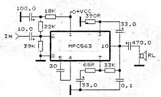 |
| 4 - 20 Volts Amplifier Circuit |
Posted in:
ICs audio amplifier
|
|
|
Rabu, 04 Mei 2011
by skemarangkaian
This is an amplifier circuit based on IC AN374 which has a 1 Watt output power with supply voltage and a maximum of at least 8 volts to 16 volts with the DC current. Following amplifier circuit 1 Watt l 8 - 16 Volts Audio Amplifier.
 |
| 1 Watt l 8 - 16 Volts Audio Amplifier |
Posted in:
Audio,
ICs audio amplifier,
Power amplifier
|
|
|
Jumat, 29 April 2011
by skemarangkaian
Amplifier circuit here is all based on the ic in the gains. Three IC TA7230P, TA7236P, TA7237AP is intregated circuit (IC) which was applied to the power amplifier. Each IC has a different output, different input voltage, all IC TA7230P, TA7236P, TA7237AP is manufactured by Toshiba.
You can see maximum minimum voltage , power output , and other
here |
| TA7230P, TA7236P, TA7237AP amplifier schematic |
Posted in:
Audio,
ICs audio amplifier
|
|
|
Selasa, 26 April 2011
by skemarangkaian
Cheap electronics component for amplifier application, it is simple to be made for speaker active . The sound quality even this Mini Amplifier TDA2030 quite satisfactory for a portable audio system.
"The series of Mini Amplifier TDA 2030 "The series of mini amplifie can reproduce the power output of 14 Watt with 8 Ohm speaker load. The series of mini-amplifier can be supplied with ource voltage of 12 volts - 15 volts DC. more details, see the following series of pictures.
Daftar komponen
Resistor:
- R1: 150KΩ
- R2: 4.7KΩ
- R3: 100KΩ
- R4: 1Ω 1W
- RA/RB: 100KΩ
Capacitor
- C1: 1µF / 25V
- C2: 2.2µF / 25V
- C3: 100nF
- C4: 22µF / 25V
- C5: 100 µF / 25V
- C6: 220nF
- C7: 2200µF / 35V
IC / Dioda
- IC1: TDA2030 or TDA2030a
- D1/D2: IN4002
Posted in:
Audio,
Component's,
ICs audio amplifier,
Power amplifier
|
|
|
Sabtu, 23 April 2011
by skemarangkaian
TDA7384 - 4 x 22W car power amplifier

If connect to car battery where operating voltage is about 13.2V, then each channel can give 22W(4Ω) – what is more than enough for me. This amplifier I probably will use to test audio processor TDA7313 which is stil in development phase.
I didn’t find much information about this chip on the internet so I decided to built it and try on my own. As datasheets of TDA7384 says it is low distortion, low output noise, low external component count. Also has Stand-By function and Mute function. It has several protections like from output short circuit to GND or to Vs, capable to handle very inductive loads, thermal limiter, load dump voltage. TDA7384 is an AB power amplifier cased in flexiwatt25 (eagle library is included in project archive) package wich is designed for high end car radio applications. It allows rail to rail output voltage swing with no need of boot-strap capacitors.
 |
| Schematics TDA7384 |
I have followed the schematic in datasheed when building circuit. In datasheet you may also find PCB layout but it is two layered and didn’t fit to may box I’ve chosen. So I have made single sided PCB 50X100mm.
![]() |
| PCB TDA7384 amplifier |
As I put pins on PCB for ST-BY and Mute but I not using them, I connected these pins to VCC like it is shown in PCB view. According to datasheet St-By and Mute turns off amplifier if signal in input is lower than 3.5V. So it is recommended to connect these pins to Vcc if not used.
Maximum power dissipation of chip is 80W(Tcase=70ºC), so it can handle 4 channels working at power of 20W each. But of course chip in a box doesn’t have good ventilation so I’ve put a radiator to ensure that amplifier effectively dissipates heats. I didn’t try to load amplifier to maximum to se if it doesn’t heat up to much. But at normal sound level it stays warm what is normal.
 |
| On box amplifier |
Dont forget to put thermal paste between chip and radiator to ensure lower thermal resistance. And here we go – brand new power amplifier ready to go:
 |
| Already to use |
Posted in:
Audio,
ICs audio amplifier,
Power amplifier
|
|
|
Kamis, 21 April 2011
by skemarangkaian
This time I will post about datasheet of some IC that was applied to the power amplifier. Some of his IC from IC AN7143, AN7145L, AN7145H, AN .... , Up to BA5406. Here is the datasheet it in the form of images that you can download.
 |
| Datasheet IC Amplifier AN7143 - BA5406 |
Posted in:
ICs audio amplifier
|
|
|
Rabu, 20 April 2011
by skemarangkaian
Amplifier circuit with IC STK is tough and good quality. In this article an amplifier circuit with IC STK another base. Power "Amplifier 200Watt By STK4050" is an audio amplifier of the STK family with 200Watt power. To create a power amplifier with the STK4050 IC is not require many external components.
Power Amplifier uses symmetric 30Volt power supply system. Power Amplifier With this STK4050 can reproduce the power 200 Watts at 8 Ohm load spaker. In making Power Amplifier 200Watt With this STK4050 do not forget to provide adequate heat sink for the IC STK 4050 in order to avoid overheating.
 |
| Schematics Amplifier STK4050-STK4046 |
 |
| PCB Layout Amplifier |
Series Power Supply for Power Amplifier 200Watt By STK4050 been displayed in one image with a series of "Power Amplifier" 200Watt With STK4050 above. IC STK 4050 in this series there are several types on the market including STK4050II, STK4050V and STK4050.
And below is a list of STK ICs are used for a
good quality amplifier.
 |
| Datasheet STK IC Amplifier |
Posted in:
Audio,
ICs audio amplifier,
Power amplifier
|
|
|
Selasa, 19 April 2011
by skemarangkaian
20 Watts Power Amplifier circuit can be made with an IC power amplifier LM1875. IC LM1875 is a single chip power amplifier from National. 20 watts audio amplifier with LM1875 is a low power amplifier with good quality to the room.
To assemble the amplifier 20 watts with IC LM1875 component is not needed much support. 20 watts power amplifier using LM1875 IC in this article using symmetrical power supply. The series of 20 watts audio power amplifier with IC LM1875 can be used as an experiment or first project for the reader, because it is simple and assembly of high success.
 |
| Schematic Amplifier LM1875 |
LM1875 amplifier circuit with the above may result in the strengthening of the voltage up to 27dB for each channel (1 channel 1 IC). Strengthening the voltage can be changed by changing the feedback that is R5 R (on the circuit above using R 22K). But the tension reinforcement can not be less than 20 dB because it can cause oscillation. For the power supply or power supply 20 watts power amplifier rngakaian with lm1875 can use travo 2-3A with CT.
Posted in:
Audio,
ICs audio amplifier
|
|
|


