Tampilkan postingan dengan label Transistor Amplifier. Tampilkan semua postingan

600W subwoofer audio amplifier

Skema Rangkaian 600W subwoofer audio amplifier - This picture below is about my setup subwoofer amplifier with 20 CH mixer and parametric. This amplifier use transformer 10 ampere to supply the power and 3 ampere transformer use to supply mixer and parametric.Elco capacitor that i use for the transformer 10 A, only 10000uF numbered 2. The circuit of amplifiers that i use which is 600 watt mono subwoofer amplifier . And booster amplifier only use 2 Sanken transistors. See picture subwoofer amplifier assemblies below :

Looked over the side
Front view

Back top


Spirit Amplifier Schematics

Amplifier circuit built-up is pretty nice not always complex. There are a series of amplifiers that I saw a picture of the kit immediately. The circuit is quite simple, there was the most complex in the pre-amp and its protector.
Click to view larger | CSE-Circuit Schematic Electronics

How a series of ...Op-amp stage 1 is the heart of the circuit, the input stage with enough power to drive the power transistor. Sensor1 ntc & 2 can be attached to the main heatsink, this is optional so it can be eliminated, its functions to lower the bias voltage value if the heatsink overheating. There is no bias trimpot, R6 and R8 instead divide the voltage so we get <= 0.6V at the base driver tr.

If the voltage is just a little more driver transistors can be damaged and could trigger the final transistor is damaged in congregation / pairs. These transistors are used frequently broken, but after replaced by Sanken, safe. Thus the risk of the snaps without a limiter amplifier.

A pair of Q1 & Q2 transisitor drivers are the main transistor amplifier, while the other three pairs of transistors that form the current dumping circuit mode so it will work if there is a signal (especially bass). Final installation of this transistor is in the Blazer, hercules, Eti300w / new Giant. The design of this kind are designed to produce a stomping bass tones, the clarity about the number two, but here the driver transistor is working at grade A.The heat generated quite a bit because of using this mode (current dumping) plus the number of final / power transistor which is more than one pair. I used to use a minimal amount of the final two pairs of transistors to avoid this summer.

Installation of the load resistor should still be there at the foot of the emitter. R16 and C4 are usually intended to stabilize (reduce) the frequency of ultra treble.All use of Sanken transistors. Supply 63V 800VA toroid ct. Reservois capacitors used for stereo 2x 10.000uF/100VEstimated power ...500W rms at 8 ohms and 1000W at 4 ohms, but supply is limited in the 800VA transformer. Confused with a power output of this? Do not worry about who is more important than that is the loud speaker and the supply has not decreased. With the supply of the transformer between them are quite satisfied to control the speaker says 18 ".If I may be wrong image, R4-220K-C2 in parallel with 68pF

Simple Voltage Amplifier

Voltage amplifier is used to strengthen the input voltage. Voltage gain is the ratio of output voltage with input voltage. Where can we set the gain. Did this voltage amplifier applications? Alredy understand , Voltage amplifier can be used before the filter and power amplifier between the input signal and speaker. Remember again telecommunication engineering materials where the voltage amplifier is represented as a repeater in the process of data transmission.

The first thing to be done before designing the amplifier voltage gain is desired is to determine because the voltage gain is the main purpose of the voltage amplifier. By the way, the voltage amplifier is an amplifier Class A. Then determine the base sequence that is used along with transistors. In the amplifier voltage, output current (collector) is not so necessary so that the collector current labored as small as possible. All to save energy consumed. So there is no special requirement on the transistor voltage amplifier, where the collector current is set at 1% of the maximum collector current. Beta transistors that are not so influential on the quality of the amplifier (let alone use a voltage divider circuit which is relatively stable against changes in beta). The values ​​of other components can be searched with the existing formula. 

Simple Voltage Amplifier

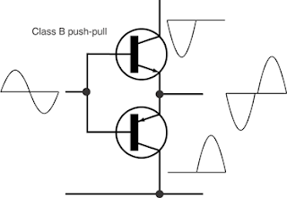
What about power amplifier? Aims to increase the power amplifier output signal power. In the course of this analog electronics, applied as a power amplifier on the speakers. At this power amplifier, the output voltage is set equal to the dc input voltage. While the current value of that changed. Does anyone know why the power amplifier, the voltage is fixed while the current is changed. I think changing the output flow is easier than changing the voltage output. And voltage range that can be applied is much smaller than the current range. Therefore it can be, the required current is very large so that in choosing a transistor must be adapted to current needs. If very large currents are needed at all, then it can be used Darlington transistor circuit. When I buy a transistor which has a large maximum collector current (about 1.5 A) appeared to form transistors is different from that so far I bought. At the center hole is used to heat sink. Heat sinks are used for fast component is not hot. By mounting the heat sink transistor then expand the surface so that heat more quickly thrown into the air. The price is relatively the same as a small power transistor. Btw, the actual power amplifier is a class B amplifier Class B amplifier is very efficient because the transistor will be active only when no signal input. Class B amplifier circuit consists of two identical transistors where each transistor is alternately brought in each half cycle. But there are drawbacks as well, the base emitter such as a diode that will be active when it has reached the forward bias voltage. So when the turn on off is not the same. Cause distortion of cross-over events. Form the output signal distortion due to cross-over is not expected that it needs considerable effort to overcome them. The solution is to arrange for the active transistor so that the need for constant base current (very small) even when it brought the transistor is not named as a class AB amplifier circuit.