Tampilkan postingan dengan label Tone control. Tampilkan semua postingan

Crossover types

Crossover is a tool that serves to limit the "frequency range" to be received by the speaker. Crossover is used to regulate flow to the tweeter, the midrange, midwoofer, and bass to the subwoofer. There are two kinds of crossover, the crossover passive and active crossover.
how the passive crossover, the type of crossover types, crossover types, the types of rosover
passive crossover 
Passive crossovers work after receiving the output of the amplifier, are ineffective because they are throwing power amplifier, because the passive crossover frequencies have been processed in the "boost" (increase) by the amplifier.

passive crossover
active crossover 
Active crossovers work so signal generated by the head unit (pure signal), dividing it in accordance with the desired frequency boost later in the amplifier, so that the amplifier to work more efficiently, and frequencies produced more organized in accordance with their respective purposes, tweeter, midrange, woofer , subwoofer.

A little short in the use of an active crossover is the use of 12V power, ground, and remote. In theory this could lead to "noise" on the audio system, but do not worry, by the proper installation, and use good quality products will not occur a problem, as in any "competition-level car audio system". If you want to raise just a little audio sound quality, passive crossover is the right choice. But if want the sound quality is really good you should select an active crossover. Active crossovers require special mounting, especially for power cables and ground wires, but the effort is proportional to the quality of music produced. Active Crossover works by "cutting" is not frequency necessary before the "boost" by the amplifier, so the amplifier can focus on the frequency you want to hear, so do not waste energy Power.

Rangkaian Audio Tone Control

Bass-treble tone control circuits
Features:

  • Wide supply voltage range, 9V to 16V
  • Large volume control range, 75 dB typical
  • Tone control, ±15 dB typical
  • Channel separation, 75 dB typical
  • Low distortion, 0.06% typical for an input level of 0.3 Vrms
  • High signal to noise, 80 dB typical for an input level of 0.3 Vrms
  • Few external components required
Note: Vcc can be anything between 9V to 16Vand the output capacitors are 10uF/25V electrolytic.

the circuits provide some additional control over tone. They were origionally intended for use with synth modules but could be easily incorporated into most any effects circuit
Tree band aktiv tune control
A tone control circuit made with a single op-amp and having three ranges, bass, middle and treble controls.

5 Band Equalizer

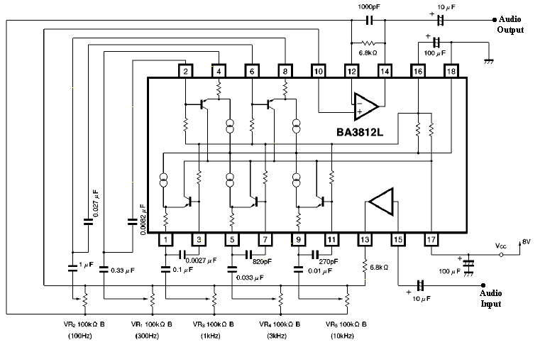
BA 3812 chip 5 Band equalizer

Rangkaian 5 band equalizerSkema Rangkaian 5 band equalizer

In this part of the investigation in a series of 5-band Equalizer circuits with a single IC BA3812 L. a device used in the hi-fi. IC BA 3812 This is with 5-point Equalizer with all the functions integrated in one IC.

Equalizer has advantages, namely: small distortion, a small noise, dinamic local area, and is suitable for a series of hi-fi stereo. And with a wide voltage range from 3.5 volt to 16 volt. Voltage is the recommended 8 volt but according 9volt highest voltage.
The following 5 frequency channels from this series:
  • 100 hz
  • 300 hz
  • 1 khz
  • 3 khz
  • 10 khz
5 band simple Equalizer

Rangkaian 5 band equalizerSkema Rangkaian 5 band equalizer

Following series can be used as a 5 channel Equalizer simple cheap. Working principle of this series is a series of band pass frequency with center frequency of 10 kHz, 2.5 kHz, 625 Hz, 40 Hz and 155Hz. By using potensiometer, the value of each frequency band pass possible change.

Digital Volume Control

Rangkaian Digital Voleme Control

Rangkaian Digital Volume Control

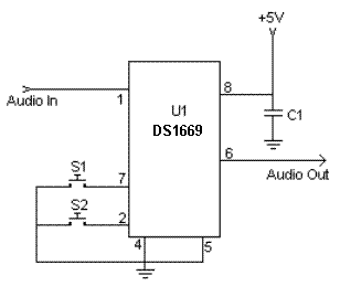
in this series can use a digital set the volume on the amplifier or tone control. although the tone control is the volume available, but we can make a volume control with a series.

to use this series, release potensiometer the tone control that serves to set the volume, and then connect the output volume of the series of digital control pin to the middle tone contrlol, input pin to the right and the left on the ground.

PIN DESCRIPTION DS1669:

RH - High Terminal of Potentiometer
RW - Wiper Terminal of Potentiometer
RL - Low Terminal of Potentiometer
-V, +V - Voltage Inputs
UC - Up Contact Input
D - Digital Input
DC - Down Contact Input

Subwoofer Pre-Amp Filter

Acoustic spectrum is extended by the 20Hz frequency is very low and reaches as high frequency 20000Hz. In the low frequency is lowered sense of direction. This reasoning leads us to attribute to the speaker's use of very low frequency. Making it to you we propose to distinguish these frequencies, in order for him to lead us on a suitable amplifier.
Acoustic filter are met at different points in the sound system. Applications knownest they are filter baxandal to organize low-and high-frequency tones and crossover filter where the acoustics are separated in the subareas, for it leads to the appropriate speakers. Applications that you can we propose is a simple filter that limits the acoustic region (20-20000Hz) in 20-100Hz region.

With manufacturing, we propose that you can you can make an active filter for you lead a very low frequency loudspeaker. With this you will put a big one between speaker HIFI speakers from you. In order for you to have a complete picture of sound you will need also an appropriate amplifier. In the entry of circuit you will connect the two roads out of the preamplifier or the exit of the preamplifier few.

The series production in order to allocate out of the facility led a series of subwoofer power. If for some reason you do not have space for you to put the third speaker in the courtroom, then you can choose a smaller speaker. This output will depend on the type of music that you hear. If in deed you have the space, then after you create a filter and still say thank you, you can he recommend your friends or still makes each other to your friends.
Circuit diagram

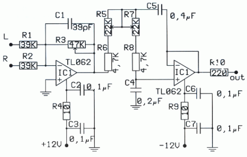
Filter | PreAmp Subwoofer
Filter | PreAmp Subwoofer circuit diagram


Parts

R1 = 39 Kohm , R2 = 39 Kohm,R3 = 47 Kohm,R4 = 10 Ohm,R5 = 22 Kohm,R6 = 4.7 Kohm,R7 = 22 Kohm, R8 = 4.7 Kohm, R9 = 10 Ohm, R10 = 220 Ohm, C1 = 39 pF,C2 = 0.1 UF,C3 = 0.1 UF, C4 = 0.2 UF, C5 = 0.4 UF, C6 = 0.1, UF C7 = 0.1 UF, IC1 = TL064

In the form that appears theoretical filter circuit. At first glance we see three different circuits which are mainly produced by two rounds of operational amplifiers. This circuit is a mixture, with the assistance variable amplifier and variable filters. Late-making requires a series of operations catering catering with the same trend with  ± 12. operational amplifier which is the active element for this circuit is the type of dual operation as a TL082 and NE5532. 

The operational amplifier is included in a family is equipped with field-effect transistor IFET in their entries. Each member is allocated a family in bipolar transistor circuits and field effect. This circuit can function in a high inclination, because of their high propensity to use transistors. Also they have the high honor rhythm elevation (slew rate), low polarization at this time for entry and little influenced by temperature. The operational amplifier has an area of 3MHz unity gain bandwidth. Another important element for them is a great choice reject noise, there are currently in the line of catering.

Price refused to greater than 80dB, their consumption is small, from 11 to 3 mA. They briefly sold internally with eight pins and allocate two operational amplifiers, In the same row 14 pin in short they combine four operations, the trade them for sale with code TL074, TL084 and TL064, a nutshell with eight pins they sold the operational amplifier TL071 TL061 kajTL081 . In manufacturing we use the TL082 that has two operational. First operation of TL082 he worked as an amplifier and mixed with two channels, the entry is negative, it is a little mixed with the two resistances. A potentiometer on the steps of determining the aid circuit. At this point the left wing and right-channel preamplifier they added means of two resistances. En operational continuity with the help strengthen the signal is made depending on the price that has been potentiometer.

Filter | PreAmp Subwoofer
PCB layout

Place runner comparable with the assistance of the circuit. The second operational amplifier is a filter manufacturing. Filters from the acoustic frequency from second grade and he made a round of operational amplifiers. This filter section with variable frequency low-cut. This frequency can be changed and took the price of very low frequency of 30Hz or still exceeds 150Hz. The frequency of the filter depends on the price cuts that have circuit elements. Change the value of the elements that we can have a frequency cut 150Iz, 130Hz, 100Hz, 7A? Z, 6A? Z even 3A? Z, is the price that they can be achieved by simple rotation of the double potentiometer. Filter circuit has been made about an operation 'that has completed a TL082 dual operational amplifier. In the filter out we will connect the plug load which is connected amplifier. In a series of exit are presented, which are limited as to the extent of frequency, the signal applied in the entry of the circuit.

2 way Active Crossover

Therefore this architecture represents the simplest access I could booty and still get the adapted outcome.The band akin audio arresting enters the absorber area it is astern out of phase.This is to atone for the filters which will alter the appearance afresh appropriately abiding the arresting to it’s able phase. The filters are more-or-less accepted low and aerial canyon filters appropriately however, added capacitors and resistors accept been added in adjustment to get the altruism bottomward to a minimum appliance alone E12 components.


This alive Cantankerous over is adequately beeline forward. It consists of a absorber and two 3rd order, 18 dB per octave filters. One low canyon and the added high. The cantankerous over abundance is set at 2Khz and is advised for AEK’s 400watt per access PA/Keyboard Amp systems. Obviously alone one access is apparent here.

This ambit may not be of awfully abundant use to anyone as it was accurately advised to clothing the applications. It is not capricious or switchable for two reasons. Firstly, it didn’t charge to be back the backdrop of the apostle arrangement were already known. And secondly, the added complication was put into the accurateness of the crossover rather than it’s flexibility. The filters are akin in account to anniversary added as able-bodied as can be accepted appliance alone E12 components. If switching were to be active to accord a ambit of abundance options, a accommodation would accept to be fabricated on clarify accuracy.

The alone added way to accomplish a accepted crossover architecture and advance accurateness would apparently be to use Switched capacitor clarify architecture blocks. In theory, two 18or 24dB per octave filters could be complete such that they tracked anniversary added by actuality bound to the aforementioned clock. This would be a nice agreement but I haven’t had the befalling to prove this technology for this affectionate of application. My primary affair was the breach through of switching babble appliance such a design.

3 Band Tone Control Circuit

3 Band Tone Control circuit uses an op-amp as an amplifier end. Tone Control circuit is a regulator of tone bass, midrange and treble or 3 band called because it can set the three tones. Filter circuit is applied to the series of "Tone Control 3 band" This type baxandal like the title of this article. 
Results filtering regulator tone or tone control baxandal type is good, because there is no signal level is wasted directly into the ground. Range frequency tones generated from Tone Control 3 band was determined by the configuration of the R and C of the filter section baxandal. As an amplifier on Tone Control The set of three band use traditional IC LF351 has slewrate high and high input impedance. For more details, series 3 Band Tone Control as follows.


Figure Series 3 Band Tone Control


3 band tone control


3 Band Tone Control circuit above using LF351 Op-Amp is used to strengthen the signal after filtering by the filter process baxandal. Level tone Bass, Midrange and Treble settings are determined by potensio R1, R2 and R3. Frequency filter in the circuit above baxandal to 50 Hz bass tone, tone Midrange 1 KHz and 10 KHz for Treble tone.

Tone control low noise circuit

Tone control or pre-amplifier is an amplifier circuit supporters. Sometimes some of us do not know where a good amplifier, a raft alone and the results are not much different or even the same. Therefore we must know the character of the advantages and disadvantages of each amplifier equipment.

Tone control low noise here does not mean without noise, but noise compared with the lowest tone control on the market, for example Ronica transistor 4, TL-084, TC-2 LM833 etc.

CSE | Circuit Schematic Electronics

Jump toexplanation of each component ...

Potensio 1 serves to regulate the intensity / level of the incoming signal is assisted potensio 2 as balance / counterbalance. Potensio 2 is still installed and is usually an optional component. 1-2uF/250V capacitor R1 is actually a brand name,but I prefer to replace it with a 1K resistor / 5% normal for reasons to avoid hum and interference sensitive. R2 R3 while minimizing interruption to adjust the impedance OP-amp 1. R4 and R5 serves to increase the gain of 1.3 times. Pre amplifiers typically use a strengthening standards by 2 times, but by most of us think it has a noise. So I chose the value of 1.3 times, but the most minimal noise signal from the volume is enough to make the lamp light peak.

For low noise ...Cause of noise in op amp 1, apex audio even eliminate this stage. CanThis step is also used as a buffer (jumper R5), the strengthening of a time. Lower values ​​increase the value of R5 or R4 with consequent gains to be less, but remains at a value above 1 times due to input non-inverting path to take, so that the signal and noise can be reduced. R4 can also be replaced with a 10K trimpot and middle leg into the bass range adjuster (bass resonance).

C1 and C6 as a filter to reduce the treble / high frequency of excessive or often called oscillation prevention. R6 is actually an optional component of the impedance a little help customize the system. Ideally the same as the R8 R7 to facilitategive the sign of the gain on potensio panel tone control. C2 and C3 form a series circuit treble filter (high pass filter), its value is greater then the sound that passed the mid. C4 and C5 assisted by R9 and R10 form the low pass filter (filter bass), the greater the value of C is a bass sound that will be missedthe soft / low (maximum of 47nF), the smaller the value of c is the bass signal that is passed will further dip (dig-dig, c4 = c5 = 22nF). This value is suitable for 27-33nF, 47nF instead (depending on taste). Pot 3 & 4 pot set treble and bass levels, the greater the greater the value of this potensio gains (bass & treble including potensio volume). R11 adjusts the output impedance, while the R12 and the red LED indicator that shows if the amplifier Peak has been given a full signal.

15V maximum supply. TL074 IC can, but in designing the PCB, IC can bereplaced with 2x TL072/NE5532/4558.

Create a Digital Volume Control Circuit

This series is the volume of the digital amplifier That is used on or tone control. This series ic type using DS1669 Digital Pot IC specifically for this volume match. a series of settings used at the middle-class amplifier That small powerless under 50 watts.volum11components: C1 = 0.1uf Ceramic, IC = IC DS1669 Digital Pot, S1 / S2 = digital swicthOr you can use the series to this one:volum2The Work: The digital volume control IC uses 9.
Click to view larger.


Required to operate the series voltage regulator is 12 volts. IC1 (555) is very good to work as a flip-flop. Frequency or period can be determined with selecting value of resistor R44, R45 is combined with a capacitor C6. In this series has a 0.3 second period.IC2 is used to Decrease or increase of the calculation. In the series of this mode is used to raise up and down mode is used to Decrease the volume. 
While IC4 and IC3 has a 16-channel, analogue multiplexers, while working as an analog switch. IC3 is used as in the series of level indicator while IC4 is used as potentiometer.After the next power in the on-it, and the switch S1 is pressed to reset. When the switch S2 is pressed, the IC2 and the balance in the form of output legs responded B, C, and D in CMOS IC2. Output B, C and D control line inputs IC2 and IC3, and the chosen one, the 16-channel output, by turning on the analogue.In this series, IC4 is used as the potentiometer is connected to the That resistor 15 (R9 to R23) each of the 16 input pins and resistor / capacitor combination with C2, C3 and R7 to the output. 
Switch S2 is used to raise and switch S3 is used to Decrease the volume.Electrolyte capacitor of 1uF (C4) is used to Prevent the occurrence of noise. While the R8 and the resistor R6 is used to Prevent Tension on the half-supply voltage in order to avoid distortion of the audio signal coming from the preamplifier. Meanwhile, capacitor C2, C3 and resistor R7 is provided to filter the audio. Happy work, hopefully successfully. 

 COMPONENT LIST:

R1, 2, 3, 4: 560R R16: 1,5KR45: 150KR5: 680RR17: 3,3KC1: 0,01uFR6, 8: 100KR18: 5,6KC2, 3: 100nFR7: 1MR19: 8,2KC4: 1uF/50VR9: 10RR20: 15KC5: 100nFR10: 12RR21: 33KIC1: 555R11: 42RR22: 56KIC2: 74193R12: 100RR23: 1,5MIC3: CD4067R13: 220RR24…R39: 560RIC4: CD4067R14: 470RR40..R43: 4,7KIC5: 7805R15: 820RR44: 330KIC6 N1-N4): 7407

Improving Performance Bass Amplifier

Stereo power amplifier is less in the bass tones, but if a speaker that sounds just feels solid bass sound, there are several possibilities, the first one speaker cable upside down, try alternating bass and tone tests.
If still, you need to use 2 power supply or attempting to use this circuit. Note this circuit works for a power amp that is less power transformer with 2 speakers (stereo). One of the speaker cable (output) should be reversed, this is okay, just a game to lighten the work phase transformer from the blow bass.

We recommend that before you try this circuit, turn one speaker cable and a second test speakers with bass tones, the bass should be mutually reduce (bass-bass = 0). Next remove the driver from boknya and turn the speakers (the speaker drivers facing into the wall), the bass should grow (bass + bass = 2bass). One record store in the town of Indramayu is taking this simple way, certainly looks magnet speakers, great.

The heart of this circuit using IC with 2 op-amps, can type JRC4558, LF353, TL072, TL082, and similar. Vcc = + /-70Vdc. If Vcc = + /-42Vdc, replace the value of R9 and R10 to 2K2.
Op-amp 1 functions as a buffer, while the op-amp to-2 function as inverting the phase 180 ', both have a reinforcement of 1 times.

Improving Performance Bass Amplifier

Improving Performance Bass Amplifier

List of components:
R1, 2,5,6 .......... 100K
R3, 4 ................ 2K2
R7 ................... 100
R9, 10 .............. 2K2-3K3
C1, 2 ............... 100uf/25V
D1, 2 ............... 15V Zener
IC1 ................. TL072

1. Replace strings: strings are the source of the sound of a bass. If bad strings, of course difficult to get a good sound. How good / expensive any bass, if strings are mendem ("dead") would sound so bad


2. Know your bass character of us, whether inclined treble, middle, or ngebass (low). From here our reference point. If soundnya not in accordance with our desires, try to correction with tone control / equalizer.

3. There are so many factors affecting the bass sounds, ranging from strings, pickups, body wood, neck & fingerboard.
Try to identify the character masing2, eg the influence of wood types, pickup types, etc..
From there we can determine which one should be modified.

Chain audio a bass sound as follows
Strings-> pickup-> Preamp / Tone Control-> Connection Cable-> Amplifier
Well, just select which one would aja in mod.

Actually the material (wood) body / neck / fingerboard also influence:

String-> Body/Neck/Fingerboard-> Pickup-> Preamp / Tone Control-> Connection Cable-> Amplifier (+ Speaker)

Only if you replace the body just wrote instead of bass.
So, if you can choose a distinguished bass wood is good, Ntar if you want to be upgraded more easily.
If wood is not good (Agathis), although the results are less than the maximum upgrade.

Digital tone control with MAX5406

The series will I make here is a series regulator of Volume, Bass, and Balance Trable Digital (Tone Control). The core of this circuit is an IC-type output from the Manufacturer Maxim MAX5406, while the IC is an audio processor that comes with the interface switch hit for Tone Control setting above. The circuit scheme is as follows:

The scheme above uses very little supporting components and this makes can be made with a mini size of a matchbox only even if using all SMD components can be reduced in size by half for this time I will only give a simple layout made​​, following picture:

layout components