Tampilkan postingan dengan label Remote Control. Tampilkan semua postingan

This is a remote control circuit employing ultrasonic signals. The ultrasonic transmitter circuit is build around IC1(NE 555). IC1 is an astable multi vibrator operating at 40KHz.The output of IC1 is amplifier the complementary pair of transistors ( Q1 & Q2) and transmitted by the ultrasonic transmitter K1. The switch S1 is used activate the transmitter.

remote ultrasonicSkema rangkaian remote Control ultrasonic

Note:
  • switch S1 can be a push button switch.
  • The preset R16 can be used to adjust the sensitivity of the receiver.
  • The frequency of the ultrasonic signal can be varied by adjusting the preset R17.Adjust it for optimum performance.


The ultrasonic receiver uses an sensor transducer (K2) to sense the ultrasonic signals. When an ultrasonic signal is falling on the sensor, it produces a proportional voltage signal at its output. This weak signal is amplified by the two stage amplifier circuit comprising of transistors Q3 and Q4.The output of the amplifier is rectified by the diodes D3 & D4.The rectified signal is given to the inverting input of the opamp which is wired as a comparator. When ever there is an ultrasonic signal falling on the receiver, the output of the comparator activates the transistors Q5 & Q6 to drive the relay. In this way the load connected via the relay can be switched. The diode D5 is used as a free wheeling diode.


Features IC CA3140


  • Very High Input Impedance (ZIN) -1.5TΩ (Typ)
  • Very Low Input Current (Il) -10pA (Typ) at ±15V
  • Wide Common Mode Input Voltage Range (VlCR) - Can be wung 0.5V Below Negative Supply Voltage Rail
  • Output Swing Complements Input Common Mode
  • Directly Replaces Industry Type 741 in Most Applications
  • Pb-Free Plus Anneal Available (RoHS Compliant)


Pin Connection Ic NE 555


  • Ground, is the input pin of the source of the negative DC voltage
  • Trigger, negative input from the lower comparators (comparator B) that maintain oscillation capacitor voltage in the lowest 1 / 3 Vcc and set RS flip-flop
  • Output, the output pin of the IC 555.
  • Reset, the pin that serves to reset the latch inside the IC to be influential to reset the IC work. This pin is connected to a PNP-type transistor gate, so the transistor will be active if given a logic low. Normally this pin is connected directly to Vcc to prevent reset
  • Control voltage, this pin serves to regulate the stability of the reference voltage negative input (comparator A). This pin can be left hanging, but to ensure the stability of the reference comparator A, usually associated with a capacitor of about 10nF to berorde pin groun
  • Threshold, this pin is connected to the positive input (comparator A) which will reset the RS flip-flop when the voltage on the capacitor from exceeding 2 / 3 Vc
  • Discharge, this pin is connected to an open collector transistor Q1 is connected to ground emitternya. Switching transistor serves to clamp the corresponding node to ground on the timing of certain
  • Vcc, pin it to receive a DC voltage supply. Usually will work optimally if given a 5-15V. the current supply can be seen in the datasheet, which is about 10-15mA.

Infra Red Remote Control

Skema Infra Red Remote Control (Transmitter)
Rangkaian Remote Control ini telah dicoba dan hasilnya sangat memuaskan, alat ini bisa digunakan utk menyalakan lampu atau pesawat TV anda jaraknya lumayan jauh.


Receiver

Lay Out PCB (Receiver)

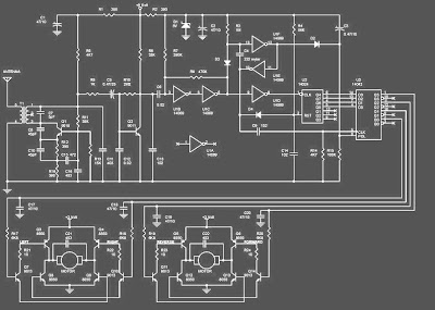
Rangkaian Radio Remote Control Mobil Mainan

In this system, radio signals emanated not continue to be raised but only when the controller sends the right / left or forward / backward, that is only a radio frequency that discontinuous,so that the credit delivery frequency radio waves.

The amount of credit that is sent to represent the command post, the forward was represented with 8 credits, left represented with 16 credits, 32 credits right and Backward 64 credits. Commands can be sent is a combination of 2 commands, namely the combination of forward / backward and right / left, as an example can be sent forward and the left, in this case the amount of credit that is sent 24, the Answer of the forward and the balance of 8 the left as many as 16 credits.

Radio Control transmitterSkema Rangkaian Pemancar Radio Remote Control
Radio Control recieverSkema Rangkaian Penerima Radio Remote Control

Making transformer TX and RX:
Transformer T1 in series transmitter and recipient, is the same, and must be made. Transformer was built using plastic koker transformer (spare part radio) so that the step appears to have 5 channels that can be filled with a wire coil, as shown in the picture. Wearing this koker facilitate scrolling wire transformer. If it can not be koker like that, just use the normal. Koker transformer is small and ferit is also small (3 mm) as the first assembly is often used for CB 27 MHz radio.

Transformer wire to wire to use in the unloading of koker, and slowly open the wire coil inside the existing wire koker because it is quite smooth and easy to drop out
  • coil wire from the foot of the number to 5 feet 4 hours direction (CW) of 3-and-roll at level 1 (line at the bottom line above)
  • Scroll through the wire from 1 foot to 2 feet clockwise roll of 4 on the exact level 2.
  • Continue to roll (from step 2) clockwise a quarter roll of 3 to 3 feet in three levels. (You can set exactly a quarter roll, because the path that has kokernya be split into 4).
Making coil L1
Scroll through the copper wire diameter size of 0.3 - 0.5 mm of 10 quarter roll koker in diameter about 4 mm (which will be released later) is also clockwis

Making coil L2
Scroll through the copper wire diameter of 0.1 mm sizes of 50 on the roll without koker plastic ferit diameter about 3.5 - 4 mm (search item from the plastic material used) is also clockwise. The length of the coil along liputi in 5 mm.

5 Channel Radio Remote Control

TX-2B / RX / 2B  5 channel radio remote control.

This article is about a simple 5 channel radio remote control circuit based on ICs TX-2B and RX-2B from Silan Semiconductors. TX-2B / RX-2B is a remote encoder decoder pair that can be used for remote control applications. TX-2B / RX-2B has five channels, wide operating voltage range (from 1.5V to 5V), low stand by current (around 10uA), low operating current (2mA), auto power off function and requires few external components. The TX-2B / RX-2B was originally designed for remote toy car applications, but they can be used for any kind of remote switching application.

Circuit diagrams and description.

Remote encoder / transmitter circuit.


The TX-2B forms the main part of the circuit. Push button switches S1 to S5 are used for activating (ON/OFF) the corresponding O/P channels in the receiver / decoder circuit. These push button switches are interfaced to the built-in latch circuitry of the TX-2B. Resistor R7 sets the frequency of the TX-2B’s internal oscillator. Resistor R1 and Zener diode D1 forms a simple Zener regulator circuit for providing the IC with 3V from the 9V main supply. C2 is the filter capacitor while C1 is a noise by-pass capacitor. D2 is the power on indicator LED while R6 limits the current through the same LED. S1 is the ON/OFF switch. The encoded control signal will be available at pin 8 of the IC. The encoded signal available at pin 8 is without carrier frequency. This signal is fed to the next stage of the circuit which is a radio transmitter. Crystal X1 sets the oscillator frequency of the transmitter section. R2 is the biasing resistor for Q1 while R3 limits the collector current of Q1. The encoded signal is coupled to the collector of Q1 through C3 for modulation. Transistor Q2 and associated components provide further amplification to the modulated signal.

Remote receiver / decoder circuit.

5 channel radio remote decoder

The remote receiver circuit is built around the IC RX-2B. The first part of the circuit is a radio receiver built around transistor Q1. The received signal is demodulated and fed to pin 14 of the IC. Pin 14 is the input of the built in inverter inside the IC. R2 sets the frequency of the IC’s internal oscillator. O/P 1 to O/5 are the output pins that are activated corresponding to the push buttons S1 to S5. Zener diode D1 and resistor R12 forms an elementary Zener regulator for supplying the RX-2B with 3V from the 9V main supply. C12 is the filter capacitor while R11 is the current limiter for the radio receiver section. Diode D2 protects the circuit from accidental polarity reversals. C15 is another filter capacitor and C14 is a noise by-pass capacitor.

Notes.

  • This circuit can be assembled on a vero board or a PCB.
  • Use 9V DC for powering the transmitter / receiver circuits.
  • Battery is the better option for powering the transmitter / receiver circuit.
  • If you are using a DC power supply circuit, it must be well regulated and free from any sort of noise.
  • Both ICs must be mounted on holders.

Interfacing relay to the RX-2B output.

The method for interfacing a relay to the output of RX-2B is shown below. When push button switch S1 of the transmitter circuit is pressed, pin O/P1 (pin 7 of the RX-2B) goes high. This makes the transistor 2N2222 to conduct and the relay is activated. The same technique can be applied to other output pins of the RX-2B. The relay used here is a 200 ohm type and at 9V supply voltage the load current will be 45mA which is fine for 2N2222 whose maximum possible collector current is 900mA. When using relays of other ratings this point has to be remembered and do not use a relay that consumes a current more than the maximum possible collector current of the driver transistor.
transistor relay driver
Interfacing relay to the remote decoder

Rangkaian Remot Kontrol Sederhana

Skema Rangkaian Remote Control Transmitter
By using the NE 555 and LM 567, we can make the system infra red remote control. Remote control works based on this reading frequency signal that is sent, so that the transmitter frequency signal must be the same as the receive frequency. Frequency on the remote control transmitter is determined by the value R1 and C1 based on the following equation:


As mentioned above, the remote control must have the same frequency with the frequency transmitted by the transmitter scheme. Recipient of this frequency range can be determined with the following equation:

Skema Rangkaian penerima Remote Control

To simplify the process of tuning, R1 at the recipient install a remote control in the variable resistor (VR). while the transmitter constant value (resistor still/ normal). If a series of remote control has finished in the raft, to know whether a series of working well, the first step must be done is make tuning, with the transmitter is turned on continuously, while R1 is set so that the recipient can detect the signal transmitter. If the tuning is successful, the relay recipient will remote control switch position, when it has happened means that a series of remote control is working well. to the next can try pressing the switch on the remote control at the sender (transmitter). should switch on when the press situation relay at the remote recipient will move poles