Home » Posts filed under Power Supply Circuit
Rabu, 11 April 2012
by skemarangkaian
Circuit Skema Rangkaian - The stabilizer circuit of the IC 78XX and 79XX commonly used for voltage stabilization with a mini PCB design , and practical. In the picture above is looking from top the PCB, with a width of 2 cm and 5 cm height. For input voltage can be directly through the AC because i've put it four rectifier diodes are then forwarded to the Elco and IC , that has a stable output in accordance with IC series. What if the IC series 7805 and 7905 , the output voltage of 5 Volts. If the series IC 7812 and 7912 then the output voltage of 12 volts , and so on. See circuit schematic below :
Part List :
D1,D2,D3,D4 = 1N4007
C1,C2 = 1000 uF/50V
C3,C4 = 470 uF/50V
IC1 = 78xx series
IC2 = 79xx series
And this is PCB design look from bottom :
PCB design by SIGMA4-Madiun
Posted in:
Power Supply Circuit
|
|
|
Selasa, 10 April 2012
by skemarangkaian
The
Adjustable Switching Regulator Circuit with LM2576 are monolithic integrated circuits that provide all the active functions for a step-down (buck) switching regulator, capable of driving 3A load with excellent line and load regulation. These devices are available in fixed output voltages of 3.3V, 5V, 12V, 15V, and an adjustable output version.
 |
| LM2576 IC Package |
Requiring a minimum number of external components, these regulators are simple to use and include internal frequency compensation and a fixed-frequency oscillator. The Adjustable Switching Regulator Circuit with LM2576 offers a high-efficiency replacement for popular three-terminal linear regulators. It substantially reduces the size of the heat sink, and in some cases no heat sink is required.
 |
| IC Switching Regulator Circuit with LM2576 |
A standard Adjustable Switching Regulator Circuit with LM2576 of inductors optimized for use with the LM2576 are available from several different manufacturers. This feature greatly simplifies the design of switch-mode
power supplies.
Other features include a guaranteed ±4% tolerance on output voltage within specified input voltages and output load conditions, and ±10% on the oscillator frequency. External shutdown is included, featuring 50 μA (typical) standby current. The output switch includes cycle-by-cycle current limiting, as well as thermal shutdown for full protection under fault conditions.
Features Adjustable Switching Regulator Circuit with LM2576 :
- 3.3V, 5V, 12V, 15V, and adjustable output versions
- Adjustable version output voltage range,1.23V to 37V
- Guaranteed 3A output current
- Wide input voltage range, 40V up to 60V for HV version
- Requires only 4 external components
- 52 kHz fixed frequency internal oscillator
- TTL shutdown capability, low power standby mode
- High efficiency
- Uses readily available standard inductors
- Thermal shutdown and current limit protection
- P+ Product Enhancement tested
Posted in:
Power Supply Circuit
|
|
|
A. Unable to start.
Can be caused by:
- No start-up voltage supply Vcc or a voltage less than 16V
- Electrolityc Capacitors supply voltage Vcc filter dry.
2. Led indicator blinking
If the supply voltage Vcc examined rocking. This is because the regulator of life and death because OVLO work., Die-protectionist regulators and auto start life over and over. If it is turned off Electrolityc Capacitors usually still keep the rest of the cargo.
Can be caused by:

- Electrolityc Capacitors supply voltage Vcc filter on a pin-4 dry. Replace with a value equal to or slightly larger. - triger UVLO
- input filter capacitor on pin-1 feed dry behind the declining value - triger OLP
- Rectifier diode of the switching transformer is damaged (sometimes when examined with avo-meter looks like a still good)
- cause the supply voltage Vcc drops of the switching transformer (UVLO)
- Part damage or broken lines on the feedback circuit of the voltage regulator through B to photocoupler - triger OVP
- Electrolityc Capacitors dry filter voltage B - triger OVP
- One of the output voltage of the switching transformer secondaries there is a short (over load) - triger OLP
- Soft start capacitor value decreases - triger OLP
3. Noise arising (noise)
Can be caused by:
- Transformer windings slack.
- If there are ceramic capacitors - can sometimes cause interference noise due to its characteristic piezoelectrik like crystal resonator. Replace with film capacitors.
4. When the st-by normal stress. But when the power is on the regulator directly off protectionism no voltage on the secondary this part. Electrolityc Capacitors are still storing charge.
Can be caused by:
- Sensor OVP small value resistor on pin-2 to the ground so that the value of delayed triger to OLP or OCP.
- Regulator IC is damaged
---------------------------------------------------------------------------------------------------------------------------
Note: Be careful when the regulator is not working. Because of Electrolityc Capacitors may still have a charge when turned off.
Posted in:
Power Supply Circuit,
Television,
Tutorials
|
|
|
The meaning STR in this article for example is a Sanken regulator series and Fairchild series STR-F/G/W KA05Q Is an ic Quasy Resonant Flyback (QRF) Swiching Regulator comprising (a) control IC and (b) power MOSFETs that are packed into a single unit. The regulator is designed so that only requires a few external components.
How it works :
A. UVLO (under voltage lock out)
Regulators will start working when the voltage Vcc start-up on pin-4 reaches 16V. Once the power supply voltage Vcc further work will be reimbursed through a switching transformer supplied from a diode rectifier. At the time the circuit was working when the voltage Vcc is less than 15V, the regulator controls will still work. regulator will stop working (protectionism) if the supply voltage Vcc drops to less than 11V.
2. Feedback control (pin-1)

PWM regulators work using the system, wherein the output voltage B + to stable controlled by the feedback circuit of the output voltage B + >>> >>> photo-coupler pin-1. A capacitor mounted on the pin-1 is used to prevent noise disturbance if anyone does not interfere with the working system.
3. Soft start (pin-5)
When the power is turned on first, then the circuit has not been working behind the Uman because there is no output voltage B +. This causes a heavy current on the MOSFET start. To prevent this, the regulator is equipped with soft start circuit internally and an external filter kapasitr.
If the power supply is used to monitor for example, the frequency of the regulator needs to be synchronized. External synchronization signal can be input through pin-5's
4. Protectors
Regulators are equipped with all sorts protector.
- Over-current protector (OCP) or Over Load protector (OLP). For example, if there is damage to flyback or def yoke, it will cause the load voltage B + over. If there is such a case the regulator will die protectionism so that IC is not damaged. For over current sensor is a resistor with a small value that is placed on pin-2 to the ground.
- Short protector. If the output voltage B + short, the regulator turns off protectionism.
- Over-voltage protectors (OVP). Regulators are not equipped with a surge protector so if the feedback path disconnected can cause the output voltage of the transformer switching regulator power up or damaged .. With OVP protectionist regulator will die if the voltage supply Vcc pin-4 rise above 22.5v.
- Thermal protector. Regulators will stop working if the temperature reaches 140 degrees Celsius.
6. Auto start.
Posted in:
Power Supply Circuit,
Television,
Tutorials
|
|
|
Power supply with driver TEA1507 is mostly used by TV branded PHILIPS. Power Supply has an efficiency rate of up to 90% - thus requiring less cooling, as well as stand-by power required is less than 1 watt.
Power Supply with TEA driver is equipped with a variety of surge protector that has a high reliability - not easily damaged if any part of a damaged power supply circuit and power transistor or FET heat is not easily damaged. Power supply circuits are dapatapat working on ac input voltage between 85 up to 275v. The way it works with the driver circuit power supply TEA 1507 is quite simple, so easy tracking of damage to the circuit.
The picture above is the basic power supply circuit with TEA1507
Posted in:
Power Supply Circuit,
Television
|
|
|
Senin, 09 April 2012
by skemarangkaian
Working of Regulator with 2 Photocoupler that is :

- Photocoupler N901 - used as a coupling-off control on the regulator by mikrokontrol. Which is set high and low voltage B + (st-by at the B + voltage is low). Control of the pin-37 POWER mikrokontrol → V610 → VD913 V908 → N901.
- Photocoupler N903 - used to control on-off the regulator of X-ray circuit protector. X-ray protector circuit of flyback → VD451 → VD452 → SCR VS472. If the flyback voltage regulator over the job will automatically be turned off by N903
- To disable the X-ray circuit protector, it can be temporarily removed photocoupler N903 first. In normal conditions the voltage at the transistor V474 should be zero.
 |
| Regulator Schematics |
Trobelshuting there is no voltage for 5v st-by on the secondary :
- Disable by removing the first circuit protectors N903
- Check the voltage of 300V
- Check all transistors
- Check the start voltage of 300V by R909 >> R906 to the base of transistor power regulator
- Check the feedback C910 >> R904 (to oscillate)
Posted in:
Power Supply Circuit,
Television
|
|
|
Selasa, 03 April 2012
by skemarangkaian
Most of the circuit power supply failure alarm circuits require additional or external power supply. However, this circuit requires no additional power supply. The circuit uses a voltage of 5 volts to 15 volts. To adjust the voltage of this circuit, first connect the power source (5 to 15V) and change the position of potentiometer VR1 until the buzzer buzzer On to Off position.
If the power supply fails, resistor R2 will bias the transistor and the base will turn on the buzzer. Here is a picture series of power supply failure alarm :
 |
| Power Supply Failure Alarm Circuit |
Posted in:
Power Supply Circuit
|
|
|
Selasa, 27 Maret 2012
by skemarangkaian
UPS design of the model is divided into several types that produce different performance characteristics:
A. Standby
2. Line Interactive
3. Double Conversion On-Line
4. Delta Conversion On-Line
Standby UPS typesThis type is commonly used by home users for the Presidency with their PC. UPS to be able to do this type of filtration against power failures and flow management, in addition to design efficient, small size and inexpensive.
Line Interactive UPS types

UPS is the type most often used in small business unit, web developer, and a number of servers located in government departments. Because, in addition to having high levels of reliability, this type also have the ability to adjust the voltage that is sufficient
fine.
UPS has an inverter is always connected to the output of the UPS system to convert the power from batteries into AC. In normal circumstances, the Inverter will perform battery charging. While in a state of power outages, Transfer Switch will close and drain power from the batteries to the UPS output. Position that is always connected to the inverter output filter provides additional power. This makes the type of UPS is widely used for server and electrical conditions are not too good.
Double Conversion type UPS On-Line
This type is most common for UPS with power more than 10kVA. These types have in common with the type of Standby. Only this type has a power source located on the inverter, not the AC power source. In this type, the main electricity supply interruption will not trigger a transfer switch for the incoming AC power to the central input to charge the batteries that provide power to the Inverter located at the output. Therefore, when the AC power is disconnected, the flow of energy will be transferred immediately without taking a break when the transfer occurs. This type of UPS above shows the performance of the average. Can be said of this type of approach the ideal of a UPS, unfortunately this type of heat is high enough.
UPS type Delta Conversion On-Line
Almost the same as the Double Conversion type, type Delta used to always supply voltage Inverter. When the power supply is interrupted, this type do the same with Double Conversion type. Delta Conversion has two functions, the first is to control the input power characteristics. While the second function is to control the input current to direct the process of charging the battery system. The thing to remember is to minimize this type of energy is wasted. In addition, it has a high compatibility to various types of generators and reduce the need for the use of cables.
Posted in:
Power Supply Circuit
|
|
|
Uninterruptible Power Supply
UPS is basically composed of three main components, namely:
This section is used to transfer circuit and battery charging. Rectifier-charger circuit block is going to supply the power needed by the inverter under full load and at that time to maintain the charge in the battery. Besides these blocks must have the ability to drain the power output of 125-130%.
Characteristics of the batteries also need to be taken into account in its charger circuit design because if a rechargeable battery with a current that exceeds the capacity limit will be able to shorten the life of the battery. Usually for a battery charging current to the UPS is 80% of current conditions issued by the batteries at full load.
Limitation of a UPS system is good by the standards of NEMA - National
Electical Manufacturer Association - is able to provide 100% power continuously (continuous load) and 2 hours at 125% load without a decrease in performance (damage). The battery can still be categorized as unfit for use if the condition is still capable of providing 100% power for 1 hour if the time of filling for 8 hours (determined by the manufacturing
battery).
The quality of the inverter is a determinant of the quality of power generated by a UPS system. Inverter function to change the DC voltage of the rectifier-charger circuit into AC voltage signal in the form of a sine wave formation and after going through the filter circuit. The resulting output voltage must be stable both voltage amplitude and frequency, low distortion, there are no voltage transients.
In addition, the inverter system needs a feedback circuit (feedback) and the regulator circuit to maintain constant voltage to be obtained.
3) Switch Shifters (Transfer switches)
Transfer switch is divided into two types, namely electromechanical and static. Electromechanical switch uses relays to get one of the supply voltage terminal and the other from the UPS system. Static switch system using semiconductor components, such as SCR.
The use of SCR would be better because of the removal operation is performed with the SCR takes only 3 to 4 ms, while the electromechanical switch is about 50 to 100 ms.
The use of UPS is done by connecting the UPS to the AC input and output PLN UPS to the load. Most UPS are used to supply the computer, because if the source of PLN suddenly dies, then the data being processed is not lost but is still in the back-up by UPS, so there's still time to save data.
Posted in:
Power Supply Circuit
|
|
|
Senin, 26 Maret 2012
by skemarangkaian
Power supply with Z2C tubes are designed specifically to provide
power supply voltage to the EL-34 tube amplifier push-pull in the previous article. Power supply with Z2C tube to tube power amplifier is made with a tube rectifier Z2C. Just as the power supply for power amplifier tube earlier, power supply also uses a filter 3 levels with kapsitor electrolyte. Circuit power supply with tube rectifier Z2C can give +210 VDC output voltage. A complete range of power supply for
power amplifier tube can be seen in thethe following figure .
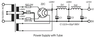 |
| Power Supply with tube |
Z2C on the rectifier tube in power supply with tube above require a supply voltage for the filaments taken from the other side of the transformer secondary. Power supply with Z2C tube is a power supply that dapt used as a substitute power supply for power amplifier tubes .
Posted in:
Power Supply Circuit
|
|
|
Kamis, 22 Maret 2012
by skemarangkaian
This is a bench top
power supply that can be used to power circuits or devices during development work in the lab. More specifically it is an adjustable, tracking, dual rail supply which means there are two supply voltages, one positive, one negative, that are adjusted by a common
potentiometer such that supply voltages are equal in magnitude. It is capable of supplying up to +/- 15V DC at up to 1A. This is sufficient for the majority of small signal electronic projects.
Dual Power Suplly Circuit diagram.
 |
| Click to view larger |
Power Supply circuit above shows the circuit layout for this project. A centre tapped transformer (TR1) is used with two 12V secondary windings with its centre tap tied to ground. This allows positive and negative voltages to be generated with respect to the central ground. Rectification follows based upon the bridge rectifier (BR1) and smoothing capacitors (C1, C2, C4 and C5).
Two linear regulators are used, an LM317 on the positive side and an LM337 on the negative side. These regulators keep the supply voltage constant for a varying load up to a load current of around 1A. The voltage adjustment is achieved through potentiometers RV1 and RV2 in the positive side of the circuit. The clever part of this circuit comes from the mirroring of the positive voltage adjustment to the negative side via the op-amp U2 to give the circuit its tracking nature.
The op-amp U2 has its positive input tied to ground via a 4K7 resistor. This means that, providing there is negative feedback around the op-amp, the op-amp will endeavour to make its negative input also at ground or 0V. The negative feedback is arranged by the output of the op-amp U2 driving the Adjust pin of the negative regulator U3 and by resistors R3 and R4. The op-amp U2 sets the voltage on the adjust pin of U3 such that the voltage at its negative input is 0V. Also as R3 and R4 are equal, the positive and negative regulated voltages must then be equal in magnitude.
An analogue meter is driven from the positive side to give an indication of the voltage setting. Two switches are used to allow the positive and negative supplies to be turned on/off independently and there are also two LED acting as indicators.
Dual Power Supply Construction
This power supply circuit was built up on Veroboard as it is quite simple to build. Heatsinks can be mounted to the two regulators to improve the current drive capability. The transformer and circuit were mounted inside a wooden box. If a metal box is used the box must be connected to mains earth to prevent a shock hazard. Figure 2 shows a picture of the finished unit. It should be noted that this box is rather shabby and the author has been meaning to improve it for a while but it does do the job nicely.
Posted in:
Power Supply Circuit
|
|
|
Kamis, 08 Maret 2012
by skemarangkaian
This series of images you can apply to make an adapter or power suplly with the output voltage (V DC output 12V). Power supply in the only protected by a capacitor as a safety if the power supply is connected to the load on the circuit.
So I recommend using 35V capacitor with a minimum specification. The security of power supply to power the more we can menggunakkan transistor TIP, but I have not discussed it. To the diode bridge can be compiled from the 4 then you solder the diode bridge rectifier into one or you can buy a bridge rectifier so that the comb-shaped (sideways) or the box. At least I would suggest using a diode bridge 1 Ampere, in a series of adapters, the bigger the better course of ampere diode current in the circuit. Diodes like toll roads, and current as a car passing by. The larger and the width of the existing highway, the faster the flow of runs and through the circuit.
For the circuit power supply 5 V, you can change the volt regulator on the type 7805 and 7905. This application applies equally in this series. For variations such as fuse or circuit switch on / off you can try it yourself.
Transformer 18 V + - 1 A minimum CT
Minimum of 35 V + Capacitor
Posted in:
Power Supply Circuit
|
|
|
Minggu, 01 Januari 2012
by skemarangkaian
Basically adapter, power supply and charger circuit has a similar construction which consists of a transformer, rectifier (rectifier) and smoothing the voltage. For there is usually an additional power supply voltage stabilizer of voltage regulator IC LM series 78XX or 79XX .
Below is a schematic circuit adapter, power supply, or battery charger (for gadgets, mobile phones, MP4player, smartphone) that is equipped with a 5V voltage stabilizer:
 |
| Adapter, power supply and charger circuit |
Posted in:
Charger Circuit,
Power Supply Circuit
|
|
|
Sabtu, 21 Mei 2011
by skemarangkaian
170 Watt power amplifier is a power amplifier that is built by IC LM4651 and LM4652.
Part of this power amplifier driver using the LM4651 IC designed specifically for the purpose of the class AB amplifier driver with short circuit protection feature, containing under voltage, thermal shutdown protection and standby functions. Section 170 Watt power amplifier using LM4651 IC with a MOSFET power amplifier is equipped with temperature sensors that will be used by IC LM4651 as controlnya thermal signal. IC IC LM4651 and LM4652 are designed specifically to each other in pairs to create a class AB power amplifier with protection features are detailed. Detailed series of 170 Watt power amplifier can be seen in thethe following figure .

Power amplifier circuit requires supply voltages +22 V DC symmetrical 0-22V. Power Amplifier with IC LM4651 and LM4652 are often used in portable HiFi systems such as powered speakers, power subwoofer and car audio power Booter. D1, D2, D3 and D4 in series 170 watt power amplifier with LM4651 and LM4652 is a 22V zener diode.
Posted in:
High power amplifier,
Power Supply Circuit
|
|
|
Tube Power Amplifier 35W Push Pull is made using a tube and eventually compiled configuration push-pull amplifier. Tube Power Amplifier 35W Push Pull tube til it using EL-34 as the amplifier end.
In the power amplifier that is made with a tube at a glance looks simple because the use of active components that are not complex. It should be noted that the use of tubes in Tube Power Amplifier 35W Push Pull require a high voltage supply, therefore in the process of making and finishing must be careful of high voltage and radiation. Detailed series of Tube Power Amplifier 35W Push Pull can be seen in the following figure.
Tube Power Amplifier Series 35W Push Pull
Sign Components Tube Power Amplifier 35W Push Pull
R1 = 470K 0.5 W
R2-5 = 2K2 0.5W
R3 = 150K 0.5W
R4 = 220K 0.5W
R6-10 = 56K 0.5W
R7 = 3.9K 0.5W
R8 = 220R 0.5W
R9 = 1M 0.5W
R11 = 39K 1W
R12-23 = 180K 0.5W
R13-21 = 820K 0.5W
R14-22 = 5K6 0.5W
R15-20 = 680K 0.5W
R16-19 = 100K 0.5W
R17-18 = 3K3 1W
R24 = 470R 2W
TR1-2 = 470R 1W Variable (adj. 270Ω)
C1-3-6-7 = 0.1uf 630V
C2 = 220pF 600v
C4-5 = 16uF 550V
C8-9 = 0.1uF 630V
C10-14 = 0.47uF 630V
C11-13 = 25uF 40V
V1 = E80CC
V2 = E80CC
V3-4 = EL34
Rectifier tube = Z2C
Audio Transformer for T1 = 2x EL34 Push Pull
Power amplifier with tubes often become the choice for a small slewrate so that the resulting audio quality is guaranteed. Tube Power Amplifier 35W in the circuit that is required to supply a high DC voltage is +220 VDC ddengan order to work properly.
Posted in:
Power Supply Circuit
|
|
|
Power supply for EL-34 tube is specially designed for the purposes of power supply at the push-pull amplifier with EL-34 tube as in article 35 Watt Tube Power Amplifier Push Pull before.
Power supply for EL-34 tube amplifier is made with transformers CT and 2 pieces diode as rectifier. Mechanical filters are applied in the power supply uses 3 levels. Power supply for tube power amplifier can deliver output voltages +220 VDC. Circuit details can be seen in the following figure.
The above power supply circuit has a high output voltage so that need to be considered in the manufacture and perakitanya because electricity can tesengat (stun). Power Supply For Tube Power Amplifier With Diode EL-34 was created specifically for the power amplifier tube push pull EL-34.
Posted in:
Power Supply Circuit
|
|
|
Kamis, 19 Mei 2011
by skemarangkaian
Power supply circuit to generate output below were variations between 1.3V DC to 12.2V DC with 1A current.
In addition, the power supply circuit is also equipped with over-current protection or shield against belebih flow. Power supply circuit is very simple, but the quality is quite good, made her basiskan regulator IC LM723 is a pretty legendary.
Description:
R2 to set the output voltage. The maximum current is determined by R3, over-current protection circuit inside the LM723 to detect the voltage on R3, if it reaches 0.65 V, the voltage output will be off her. So the current through R3 can not exceed 0.65 / R3 although output short-circuit in his.
C3 and C4 are ceramic capacitors, as much as possible directly soldered to the PCB, this is because the LM723 is prone to oscillation that is not cool.
LM723 works with 9.5V input voltage to 40 V DC and the LM723 can generate its own current of 150mA when the output voltage is not more than 6-7V under input voltage.
Specifications:
Output (value estimated):
Vmin = (R4 + R5) / (R5 * 1.3)
Vmax = (7.15 / R5) * (R4 + R5)
Imax = 0.65/R3
Max. Power on R3: 0.42/R3
Min. DC Input Voltage (pin 12 to pin 7): Vmax + 5
Component List:
B1 40V/2.5A
C1 2200uF (3300uF even better)
C2 4.7uF
C3 100nF
C4 1NF
C5 330nF
C6 100uF
Green LED D1
D2 1N4003
F1 0.2A F
F2 2A M
IC1 LM723 (in a DIL14 plastic package)
R1 1k
R2 Pot. 5k
R3 0.56R/2W
R4 3.3k
R5 4.7k
S1 250V/1A
T1 2N3055 on a heatsink 5K / W
TR1 220V/17V/1.5
Posted in:
Charger Circuit,
Power Supply Circuit
|
|
|
Flash Lights with HT2014L
This scheme is almost the same with a flash light with LM3909. In this scheme only requires IC HT2014L as a leader, and a resistor and LED. For voltage here need ration power around 4.5 V. You can apply this series to a wider scale in comparing the use IC LM3909. For the scheme are below:
Posted in:
Charger Circuit,
LED,
Power Supply Circuit
|
|
|
Toggle switch in this article is a series of toggle switches that are controlled by infrared light. The series toggle switch is made from a combination of data flip-flop CD4013 2 units. Receiver circuit of the infrared light signals arranged with infrared receiver as found on television remote receiver. Infrared signal from remote is used as clock signals and data to the data flip-flop first. then the second flip-flop data set as a toggle flip-flop toggle the output signal is used to drive the relay. for more details can be seen in thethe following image .
Series Toggle Switch With Infra Red (IR) that is required to supply voltage range of 12VDC and the output of Toggle Switch With Infra Red (IR) is dapt used to turn on the lights or other electronic devices with DC or AC voltage source. Series Toggle Switch With Infra Red (IR) was isolated from the load that is placed for use as the final relay.
Posted in:
Intregated Circuit Amplifier,
Low voltage amplifier,
Operational Amplifier Circuit,
Power Supply Circuit,
Protector
|
|
|
Senin, 02 Mei 2011
by skemarangkaian
This DIY 12V to 220V voltage converter is build with CMOS 4047 that is the main component of this small voltage converter that transforms a 12V DC into 220V AC. 4047 is used as a astable mutivibrator, at pins 10 and 11 will have a symmetrical rectangular signal wich is amplified b 2 Darlington transistors and finally reach the secondary coil of mains transformer ( 2x10V / 60VA ).
At the main voltage converter transformer terminals it will be 220V. With the help of P1 the output frequency can be adjusted between 50Hz to 400Hz. Although this is not part of any professional dc ac converters it can be used quite effective on some home appliances.
For more DC to AC voltage converters check the related posts.
Check out the tags for more 12 Volts to 220 Volts converters.
Posted in:
Power Supply Circuit
|
|
|


