Home » Posts filed under Headphone
Jumat, 20 Mei 2011
by skemarangkaian
Class A headphone amplifier
 |
| Class A headphone amplifier |
Posted in:
Audio,
Headphone,
Power amplifier
|
|
|
HiFi Headphone amplifier
![]() |
| HiFi Headphone amplifier |
Posted in:
Audio,
Headphone
|
|
|
TDA1308T Headphone amplifier circuit
 |
| TDA1308T Headphone amplifier circuit |
Posted in:
Audio,
Headphone,
Power amplifier
|
|
|
Headphone amplifier circuit with op amp ic OPA134, 2134, NE5532, 5534.
 |
| Headphone amplifier circuit with op amp |
Posted in:
Audio,
Headphone
|
|
|
Senin, 25 April 2011
by skemarangkaian
The circuit is useful to strengthen the voice on the headphones, which is where the headphones have a stereo output is used and paralleled to some headphones. The circuit is based on the TDA2822 amplifier circuit modified to ampifier headphones.
|
Amplifier for Paralelling Headphone |
In the amplifier circuit I do not put potensio meter to adjust the size of the desired sound on headphones, I just give constraints on two 33K resistors so that the voice issued not too hard. But if you want to make the sound volume settings, you can replace the 33K resistor with potensio meters or trimpot with resistance at 50K. Input voltage in the circuit I took it from a usb DVD, PC, which berkeluaran voltage 5 V DC, which can supply chain so it can work with the good. To parallel his headphones can be seen below...
 |
| Paralel Headphone Wiring Diagram |
Posted in:
Audio,
Headphone
|
|
|
Sabtu, 16 April 2011
by skemarangkaian
Transmitter and receiver circuit using infra red audio signal is applied to emit an audio signal and will received on a headphones. Making his series is not too difficult, the transmitter and receiver circuit scheme can be seen below.
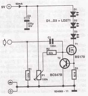 |
| Transmiter schematics |
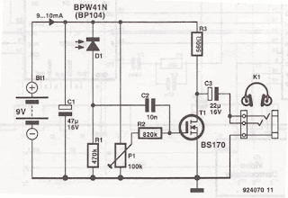 |
| Receiver schematics |
After the series finished, you can try to give the audio inputs on the transmitter and point the LED transmitter to the receiver. Maximum distance is a few meters may not be more than 10 meters, but you can listen to music without wires while using infra red.
Posted in:
Headphone,
Wireless
|
|
|
Kamis, 14 April 2011
by skemarangkaian

Commercially available hearing aids are expensive. Here is a cheap hearing aid circuit that uses only four transistors and some passive components. In moving the power switch S to 'on' position, the condenser microphone detects the sound signal, which is amplified by transistor T1 and T2.
Now the amplified signal through coupling capacitor C3 to the basic Transistor T3. Signal further amplified by T4 to a PNP transistor drive low impedance earphones. Capacitors C4 and C5 is the power supply decoupling capacitor. This circuit can be easily installed in small, general purpose PCB or Vero board. It operates off of DC supply of 3V. For this, You can use two small 1.5V cells. Continue to switch S to the state 'off' when circuit is not used. To increase the sensitivity of the condenser microphone, the house in a small tube. This fee circuit around Rs 65.
Posted in:
Headphone
|
|
|


