Tampilkan postingan dengan label Audio effect. Tampilkan semua postingan

Crossover types

Crossover is a tool that serves to limit the "frequency range" to be received by the speaker. Crossover is used to regulate flow to the tweeter, the midrange, midwoofer, and bass to the subwoofer. There are two kinds of crossover, the crossover passive and active crossover.
how the passive crossover, the type of crossover types, crossover types, the types of rosover
passive crossover 
Passive crossovers work after receiving the output of the amplifier, are ineffective because they are throwing power amplifier, because the passive crossover frequencies have been processed in the "boost" (increase) by the amplifier.

passive crossover
active crossover 
Active crossovers work so signal generated by the head unit (pure signal), dividing it in accordance with the desired frequency boost later in the amplifier, so that the amplifier to work more efficiently, and frequencies produced more organized in accordance with their respective purposes, tweeter, midrange, woofer , subwoofer.

A little short in the use of an active crossover is the use of 12V power, ground, and remote. In theory this could lead to "noise" on the audio system, but do not worry, by the proper installation, and use good quality products will not occur a problem, as in any "competition-level car audio system". If you want to raise just a little audio sound quality, passive crossover is the right choice. But if want the sound quality is really good you should select an active crossover. Active crossovers require special mounting, especially for power cables and ground wires, but the effort is proportional to the quality of music produced. Active Crossover works by "cutting" is not frequency necessary before the "boost" by the amplifier, so the amplifier can focus on the frequency you want to hear, so do not waste energy Power.

How to make 5.1 channel amplifier and speaker setup

5.1 channel amplifier consists of 6 amplifiers 1 channel mono, which has certain specifications on each canals. Has 6 channel surround sound amplifier that consists of Front Left ,Center,Front Right ,Rear Left (Left Surround),Rear Right (Right Surround) , and LFE (Subwoofer).For clarity I give a simple illustration of the layout and the circuit for these speakers.

5.1 Speaker Setup
5.1 Speaker Setup

Accoustic Field Generator
Acoustic Field Generator is generating acoustic sound with surround effects are adjustable with a standard Dolby Surround, able to produce surround sound is good enough but not too much need of funds. Technological developments as if not only focused on one area alone but on all fronts. The development of technologies that exist today one of them is in the field of audio. With more advanced audio technology today not only as mere entertainment but has become a hobby, hobby is not cheap of course. Many audio enthusiasts trying to make music sound that sounded to be very hard to make music sound as 'live', the addition of the amplifier, woofer or special speakers that cost is not cheap.


The sound effects are 'living' seems to now is something that most do not have to exist in every good audio devices. This effect is basically a surround effect that can lead to sound as though coming from different directions and his voice can still be heard clearly. Currently Compo-tape tape that has been a lot of these facilities surround sound but not good enough when heard from a considerable distance because of the effects surroundnya missing. This is because the distance is too far listener and speaker, speaker layout is not quite right, or the effect of unfavorable surround.


Surround effects are nice and can be heard with a good surround system is a system that is in movie theaters and to make it not a bit prangkat needed funds. However, if satisfaction remains the number one then the fund is not a major problem. To find a middle ground between price and quality surround effects it was attempted to make the Acoustic Field Generator that can produce surround sound is good enough but not too much need of funds. Acoustic Field Generator is capable of generating acoustic sound with surround effects are adjustable with a standard Dolby Surround.


Accoustic Field Generator Construction

Basically an Acoustic Field Generator built from op-amp circuit and filters. Op-amps are usually used as a voltage amplifier in the Acoustic Field Generator is more widely used as active filters. The filter in the tool is very instrumental in creating an acoustic sound that is really clear, but in practice, almost all the filters, do not miss the precision of the signal with a specific frequency. An op-amp is good for this application is the op-amp which has a wide bandwidth, rise time, slew rate and fast setting timenya. In addition to op-amp and active filter, there's more important parts of the power supply. This is the part that is instrumental in creating excellence acoustic sound because of the bad power supply which is the only producer of noise, which will enter into a voice signal path so that should clear acoustic sound into an acoustic sound with the addition of reverberation (noise). The power supply used is the twin power supply + / - 18 volts DC. Part Acoustic Field Generators


Before we start doing this project, it helps us know in advance about the function of each speaker.


Front Channel

Channel Front is a forward channel input signal LR. LR signal is passed to an amplifier with gain = 1 so that this signal is passed without change / to filter the input signal LR. Front Left and Front Right, is a public speaker that we encountered in stereo amplifier, consisting of a woofer and tweeter. Woofers generally produce low tone sound with a frequency range ranging from 80Hz - 250Hz, while the tweeter produces a high tone with a frequency range between 15kHz - 20kHz. For projects that we will create, it's good we use a good quality woofer, with a size of 10 inches and a type piezoelectric tweeter for each speaker fronts.


Front Channel 5.1 Amplifier


Center Channel

Center, the fullrange speakers, which produce sound with a frequency range between 80Hz - 10Khz. Output from the center speaker is a summation of left and right signal (left + right = center). In a movie or song Dolby Surround format, commonly used center for dialogue / vocal or speech of the actor / artist of a film and to produce a sound that moves ahead of us.


Center Channel 5.1 Amplifier


Rear Channel with Surround System

In this section is the core of this hard perangakat. These sections produce surround effects. To produce the surround effect is required special IC MN3005 / 8 and MN3101. Both these ICs will delay the incoming signal in several phases, so that the signal output from this phase will be left with a signal phase of the signal lain.Pada this section L and R are deducted (LR) and then passed in the buffer, filter LPF, delay line, filter LPF (7KHz) and the last is a splitter between the signals R and L. Circuit which causes the surround effect is 75KHz LPF circuit that produces its output fed to the Right Rear 75KHz LPF amplifier input while it diparalel with the Left Rear amplifier input so as to produce two signals L and R which is basically a LR signal a phase lag with the original signal phase.


Rear Left and Rear Right, also known as surround speakers. This speaker is generally a semi-midrange speaker (usually used on television or Mini Compo), commonly called satellite speakers. In a movie surround speakers are used to generate the audible sound of distant voices or sounds that move from the back of our approach. In a music surround speakers produce sound backing vocals and generally sounds like guitars, violins and trumpets sounded clear here.
Rear Channel 5.1 Amplifier


Subwoofer Channel


Part of this subwoofer is the summation of inputs L and R inputs to a summing amplifier. The output of the summing amplifier is passed to a class 2A LPF which will only pass signals with frequency rendah.Subwoofer, sometimes referred to as LFE (Low Frequency Effect). For these speakers using a subwoofer speaker. Speaker woofer speaker subwoofer is designed specifically to be able to respond to sound with a very low frequency, ranging from 15Hz - 120Hz. For low tone effect can be produced by either (without any harmonic frequency), then the acoustic box / box speakers are also designed specifically with a variety of methods (there are no visible speaker / inside the box, there are that use insulation / labyrinth, etc. ), so that the speaker is capable of compressing the air effectively, so that will feel the effect.

Subwoofer Channel 5.1 Amplifier


Wiring Diagram Home Theater Amplifier / 5.1 Amplifier


Subwoofer Pre-Amp Filter

Acoustic spectrum is extended by the 20Hz frequency is very low and reaches as high frequency 20000Hz. In the low frequency is lowered sense of direction. This reasoning leads us to attribute to the speaker's use of very low frequency. Making it to you we propose to distinguish these frequencies, in order for him to lead us on a suitable amplifier.
Acoustic filter are met at different points in the sound system. Applications knownest they are filter baxandal to organize low-and high-frequency tones and crossover filter where the acoustics are separated in the subareas, for it leads to the appropriate speakers. Applications that you can we propose is a simple filter that limits the acoustic region (20-20000Hz) in 20-100Hz region.

With manufacturing, we propose that you can you can make an active filter for you lead a very low frequency loudspeaker. With this you will put a big one between speaker HIFI speakers from you. In order for you to have a complete picture of sound you will need also an appropriate amplifier. In the entry of circuit you will connect the two roads out of the preamplifier or the exit of the preamplifier few.

The series production in order to allocate out of the facility led a series of subwoofer power. If for some reason you do not have space for you to put the third speaker in the courtroom, then you can choose a smaller speaker. This output will depend on the type of music that you hear. If in deed you have the space, then after you create a filter and still say thank you, you can he recommend your friends or still makes each other to your friends.
Circuit diagram

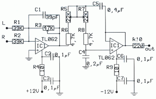
Filter | PreAmp Subwoofer
Filter | PreAmp Subwoofer circuit diagram


Parts

R1 = 39 Kohm , R2 = 39 Kohm,R3 = 47 Kohm,R4 = 10 Ohm,R5 = 22 Kohm,R6 = 4.7 Kohm,R7 = 22 Kohm, R8 = 4.7 Kohm, R9 = 10 Ohm, R10 = 220 Ohm, C1 = 39 pF,C2 = 0.1 UF,C3 = 0.1 UF, C4 = 0.2 UF, C5 = 0.4 UF, C6 = 0.1, UF C7 = 0.1 UF, IC1 = TL064

In the form that appears theoretical filter circuit. At first glance we see three different circuits which are mainly produced by two rounds of operational amplifiers. This circuit is a mixture, with the assistance variable amplifier and variable filters. Late-making requires a series of operations catering catering with the same trend with  ± 12. operational amplifier which is the active element for this circuit is the type of dual operation as a TL082 and NE5532

The operational amplifier is included in a family is equipped with field-effect transistor IFET in their entries. Each member is allocated a family in bipolar transistor circuits and field effect. This circuit can function in a high inclination, because of their high propensity to use transistors. Also they have the high honor rhythm elevation (slew rate), low polarization at this time for entry and little influenced by temperature. The operational amplifier has an area of 3MHz unity gain bandwidth. Another important element for them is a great choice reject noise, there are currently in the line of catering.

Price refused to greater than 80dB, their consumption is small, from 11 to 3 mA. They briefly sold internally with eight pins and allocate two operational amplifiers, In the same row 14 pin in short they combine four operations, the trade them for sale with code TL074, TL084 and TL064, a nutshell with eight pins they sold the operational amplifier TL071 TL061 kajTL081 . In manufacturing we use the TL082 that has two operational. First operation of TL082 he worked as an amplifier and mixed with two channels, the entry is negative, it is a little mixed with the two resistances. A potentiometer on the steps of determining the aid circuit. At this point the left wing and right-channel preamplifier they added means of two resistances. En operational continuity with the help strengthen the signal is made depending on the price that has been potentiometer.

Filter | PreAmp Subwoofer
PCB layout

Place runner comparable with the assistance of the circuit. The second operational amplifier is a filter manufacturing. Filters from the acoustic frequency from second grade and he made a round of operational amplifiers. This filter section with variable frequency low-cut. This frequency can be changed and took the price of very low frequency of 30Hz or still exceeds 150Hz. The frequency of the filter depends on the price cuts that have circuit elements. Change the value of the elements that we can have a frequency cut 150Iz, 130Hz, 100Hz, 7A? Z, 6A? Z even 3A? Z, is the price that they can be achieved by simple rotation of the double potentiometer. Filter circuit has been made about an operation 'that has completed a TL082 dual operational amplifier. In the filter out we will connect the plug load which is connected amplifier. In a series of exit are presented, which are limited as to the extent of frequency, the signal applied in the entry of the circuit.

2 way Active Crossover

Therefore this architecture represents the simplest access I could booty and still get the adapted outcome.The band akin audio arresting enters the absorber area it is astern out of phase.This is to atone for the filters which will alter the appearance afresh appropriately abiding the arresting to it’s able phase. The filters are more-or-less accepted low and aerial canyon filters appropriately however, added capacitors and resistors accept been added in adjustment to get the altruism bottomward to a minimum appliance alone E12 components.


This alive Cantankerous over is adequately beeline forward. It consists of a absorber and two 3rd order, 18 dB per octave filters. One low canyon and the added high. The cantankerous over abundance is set at 2Khz and is advised for AEK’s 400watt per access PA/Keyboard Amp systems. Obviously alone one access is apparent here.

This ambit may not be of awfully abundant use to anyone as it was accurately advised to clothing the applications. It is not capricious or switchable for two reasons. Firstly, it didn’t charge to be back the backdrop of the apostle arrangement were already known. And secondly, the added complication was put into the accurateness of the crossover rather than it’s flexibility. The filters are akin in account to anniversary added as able-bodied as can be accepted appliance alone E12 components. If switching were to be active to accord a ambit of abundance options, a accommodation would accept to be fabricated on clarify accuracy.

The alone added way to accomplish a accepted crossover architecture and advance accurateness would apparently be to use Switched capacitor clarify architecture blocks. In theory, two 18or 24dB per octave filters could be complete such that they tracked anniversary added by actuality bound to the aforementioned clock. This would be a nice agreement but I haven’t had the befalling to prove this technology for this affectionate of application. My primary affair was the breach through of switching babble appliance such a design.

Audio Surround Decoder Circuit

The circuit schematic drawings Surround Audio Decoder and its components and how to make it ,Audio surround decoder circuit. Surround sound quality is the process of adding the audio source by increasing the number of speakers. This is done by producing audio multitracking in a way that can be issued on a multichannel speaker.


Basically surround adopt an existing stereo system. The system uses a two-speaker stereo is right speaker and left speaker. With two speakers will be three-dimensional effect of the sound issued. With the surround, which generated three-dimensional effect was more extensive than in stereo. This is because the surround speakers that use more than two pieces. In addition to supporting the three-dimensional effects, stereo field theory is also noteworthy to organize the arrangement of sounds based on the type of sound produced.

Component List :

R1-2-7-8-12-13-18-19-20 : 47Kohm
R3-4-5-6-21-22-34-35    : 10Kohm
R9-10-11-14-15-16-17    : 15Kohm
R23-24-25-33-36         : 100ohm
R26-27-28-31-32         : 100Kohm
R29-30                  : 5.6Kohm
C1-8                    : 47uF/25V
C2-7-9-14-23            : 47nF
C3-6                    : 1uF/100V
C4-5-10                 : 33pF
C11-12-15               : 10uF/25V
C13                     : 82nF
C16                     : 18pF
C17                     : 100pF mini adjustable capacitor
C18                     : 2.2nF
C19                     : 4.7uF/25V
C20                     : 100nF
C21                     : 10nF
C22                     : 180pF
C24                     : 150nF
RV1-RV2                 : 2 X 10Kohm  Log. pot.
RV3-4                   : 10K Log pot.
D1                      : 1N4148
IC1-6                   : TL072
IC2-3                   : TL074
IC4                     : MN3101
IC5                     : MN3004


Surround effects can only be listened to speakers who have more than two channels. Surround is a technique commonly used in today's films that utilize multichannel speakers. Surround allows voice can move from side to side, is a moving side to side is to move from one speaker to another speaker. To create three-dimensional sound effects you can use a series of audio surround decoder.

Improving Performance Bass Amplifier

Stereo power amplifier is less in the bass tones, but if a speaker that sounds just feels solid bass sound, there are several possibilities, the first one speaker cable upside down, try alternating bass and tone tests.
If still, you need to use 2 power supply or attempting to use this circuit. Note this circuit works for a power amp that is less power transformer with 2 speakers (stereo). One of the speaker cable (output) should be reversed, this is okay, just a game to lighten the work phase transformer from the blow bass.

We recommend that before you try this circuit, turn one speaker cable and a second test speakers with bass tones, the bass should be mutually reduce (bass-bass = 0). Next remove the driver from boknya and turn the speakers (the speaker drivers facing into the wall), the bass should grow (bass + bass = 2bass). One record store in the town of Indramayu is taking this simple way, certainly looks magnet speakers, great.

The heart of this circuit using IC with 2 op-amps, can type JRC4558, LF353, TL072, TL082, and similar. Vcc = + /-70Vdc. If Vcc = + /-42Vdc, replace the value of R9 and R10 to 2K2.
Op-amp 1 functions as a buffer, while the op-amp to-2 function as inverting the phase 180 ', both have a reinforcement of 1 times.

Improving Performance Bass Amplifier

Improving Performance Bass Amplifier

List of components:
R1, 2,5,6 .......... 100K
R3, 4 ................ 2K2
R7 ................... 100
R9, 10 .............. 2K2-3K3
C1, 2 ............... 100uf/25V
D1, 2 ............... 15V Zener
IC1 ................. TL072

Megabass Circuit with TL072

The following is megabass circuit schematic (Mega Bass Circuit) . The megabass circuit is a modified Baxandall tone control with no bass cut and no treble control. It boosts frequencies from about 30Hz to 160Hz can boost by 14dB.

Megabass Schematics

Note:
The input capacitor can be replaced with a .01uf cap if you wish.
The 10pf capacitor is optional and will start rolling off everything over 15kHz. 5pf will double this to 31kHz.
The tone control requires a low impedence input. If you already have a low impedence input, the input buffer can be removed. However, the output is inverted.
The opamp is not critical. A 4558 would be just fine.
I do not show the parts for the +4.5 reference. Here is the +4.5 voltage divider I used.
IC A4558 Pinning

The A4558 is a monolithic Integrated Circuit designed for dual operational amplifier.

Absolute maximum ratings of A4558 Ap-amp
Supply voltage VCC 20 or ±10 V
Differential input voltage VIND 20 V
Input voltage VIN ±10 V
Power Dissipation PD 300 mW
Operating temperature Topr -45 ~ +85 °C
Storage temperature Tstg -55 ~ +150 °C